 WASA
Designing the Hubris drivetrain
Printed planetary gearboxes, repurposed quadcopter motors, and a rocker-bogie suspension built from aluminium extrusions.
The Hubris drivetrain is a mixture of 3D printed parts, aluminium extrusions, and hardware left over from other projects. The design started at the wheels and worked its way inwards: first the in-hub planetary gearbox, then the rocker-bogie suspension, and finally the structure that ties it all together.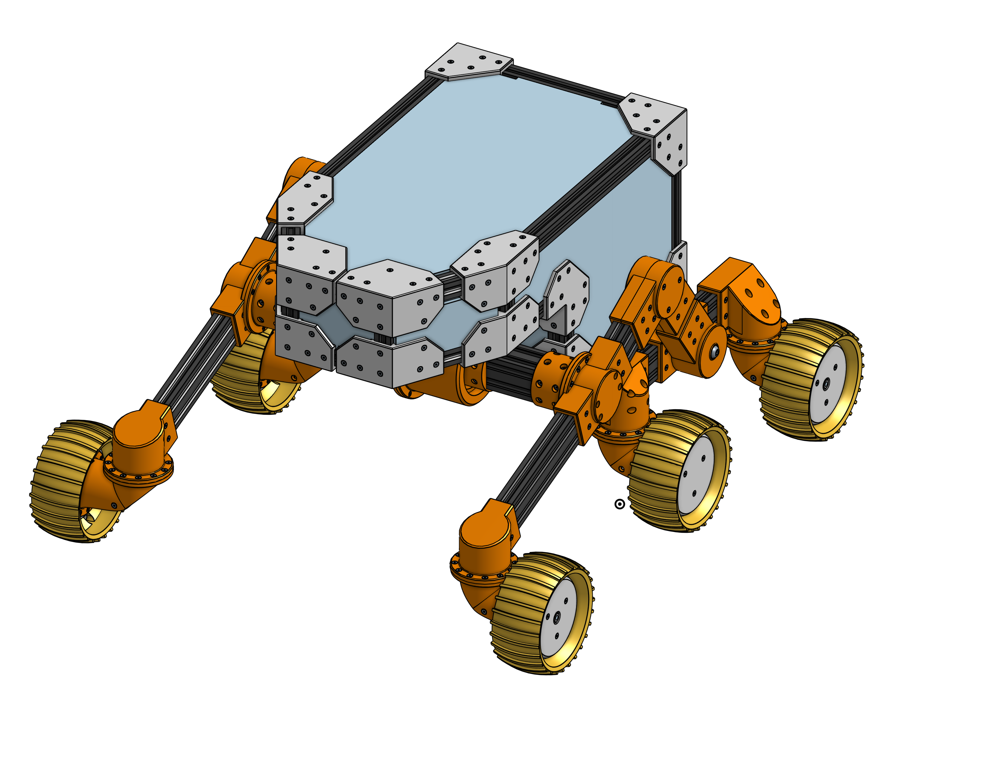
Starting with the wheels
The first thing I worked on was the in-hub planetary gearbox. The entire wheel hub is 3D printed, currently in PLA. That makes it convenient to prototype, although I don’t expect the PLA to survive long once exposed to our “Mars environment simulator”. The tyre is printed in TPU. The planet gears in each in-wheel gearbox run on standard 608 skateboard bearings.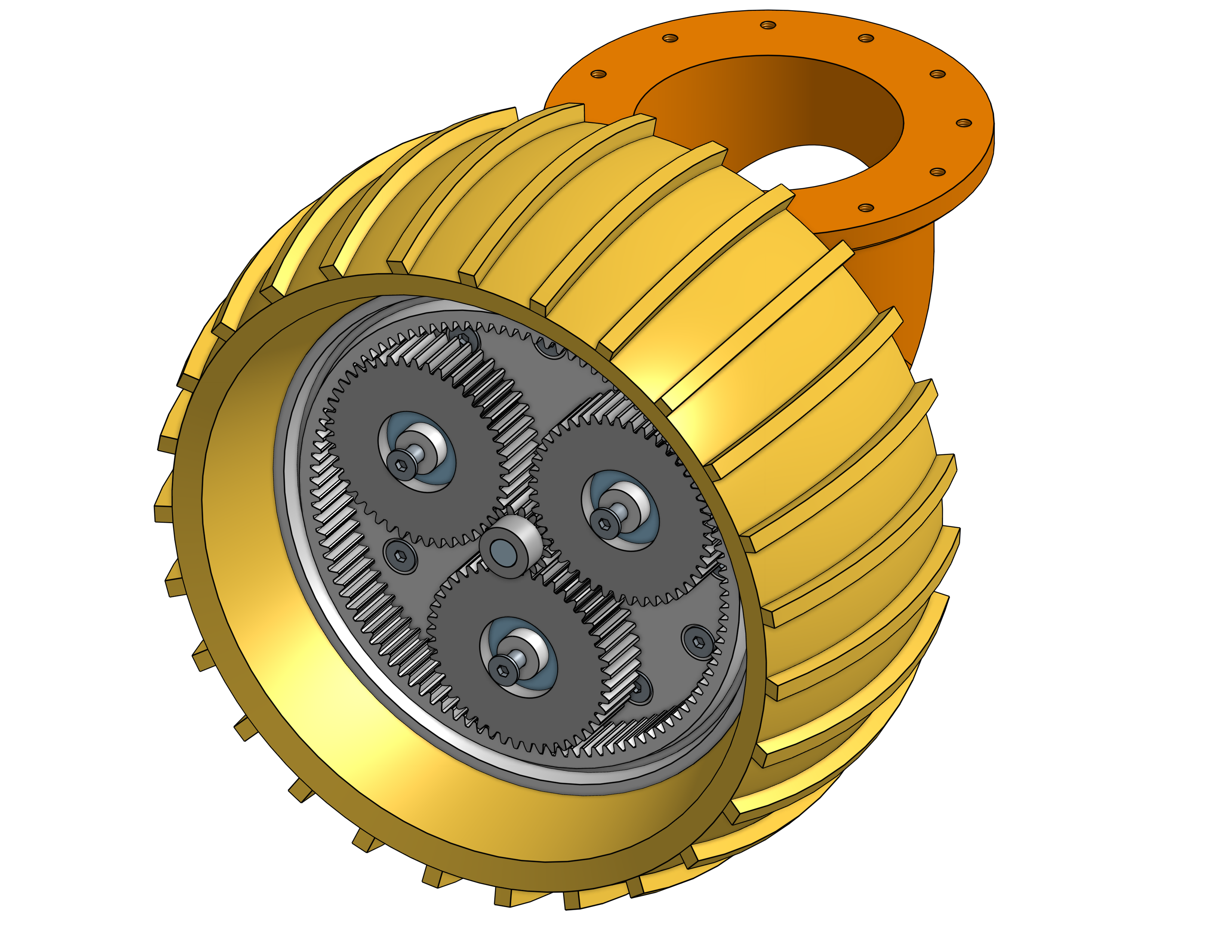
The motors are Turnigy Aerodrive SK3 outrunners, left over from a quadcopter project. That’s why the rover has only four driven wheels, despite having six wheels in total.
I’ve considered replacing them with six matching lower-KV motors. For now, though, the plan is to use field-oriented control (FOC) with two MKS XDrive boards and AS5600 sensors in a closed-loop configuration. I believe reusing the motors I already have is a more budget-efficient way to prove out the design.
Just because it’s going to “Mars” doesn’t mean it has to be gold plated.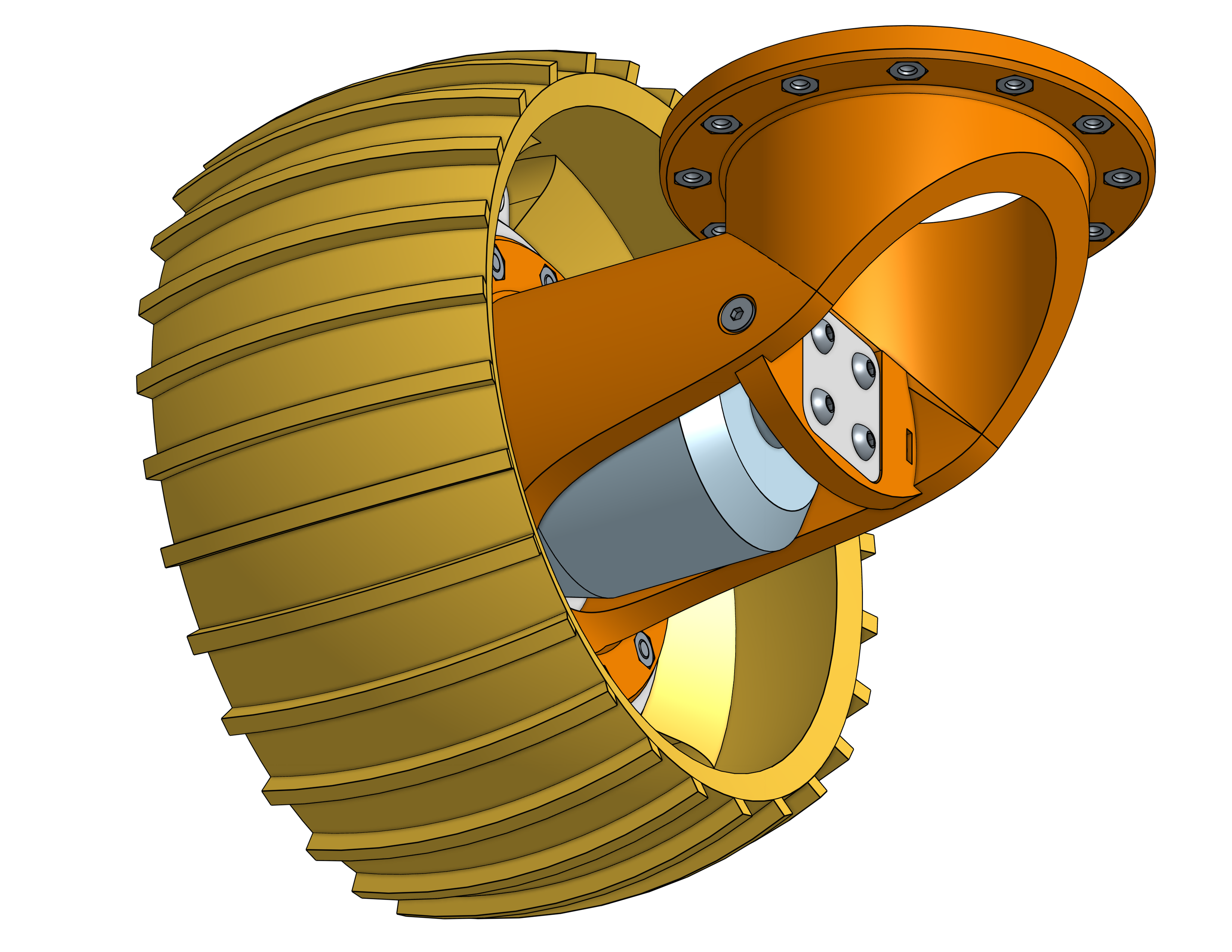
Building out the rocker-bogie
Once I knew the wheel dimensions — about 130 mm in diameter — I could scale the rest of the design to fit and continue work on the rocker-bogie suspension.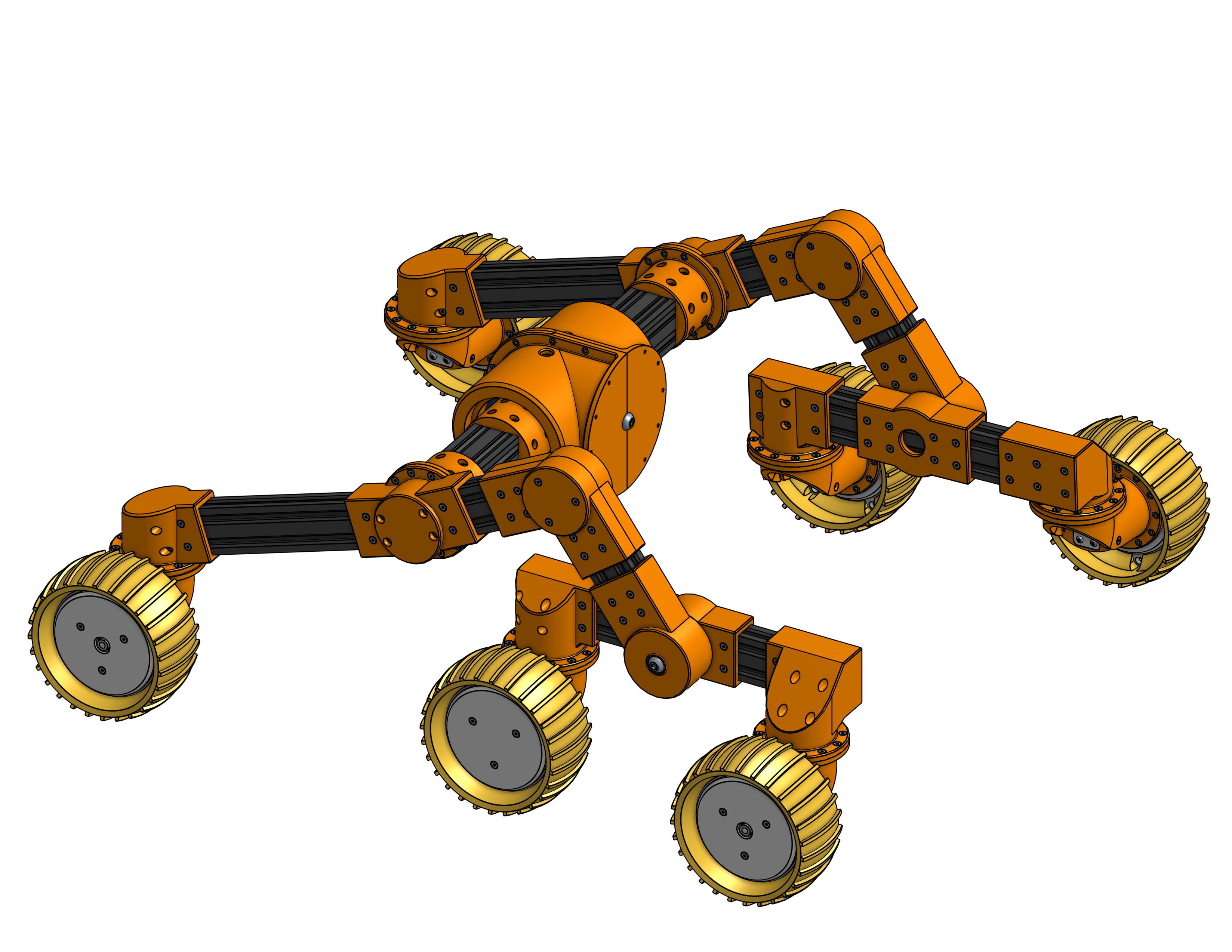
The suspension centres around a large 3D printed differential, mounted securely to the front of the main robot body. Almost all of the differential uses standard 608-sized skateboard bearings, but it also needed additional support from large 6812 bearings, shown in blue below.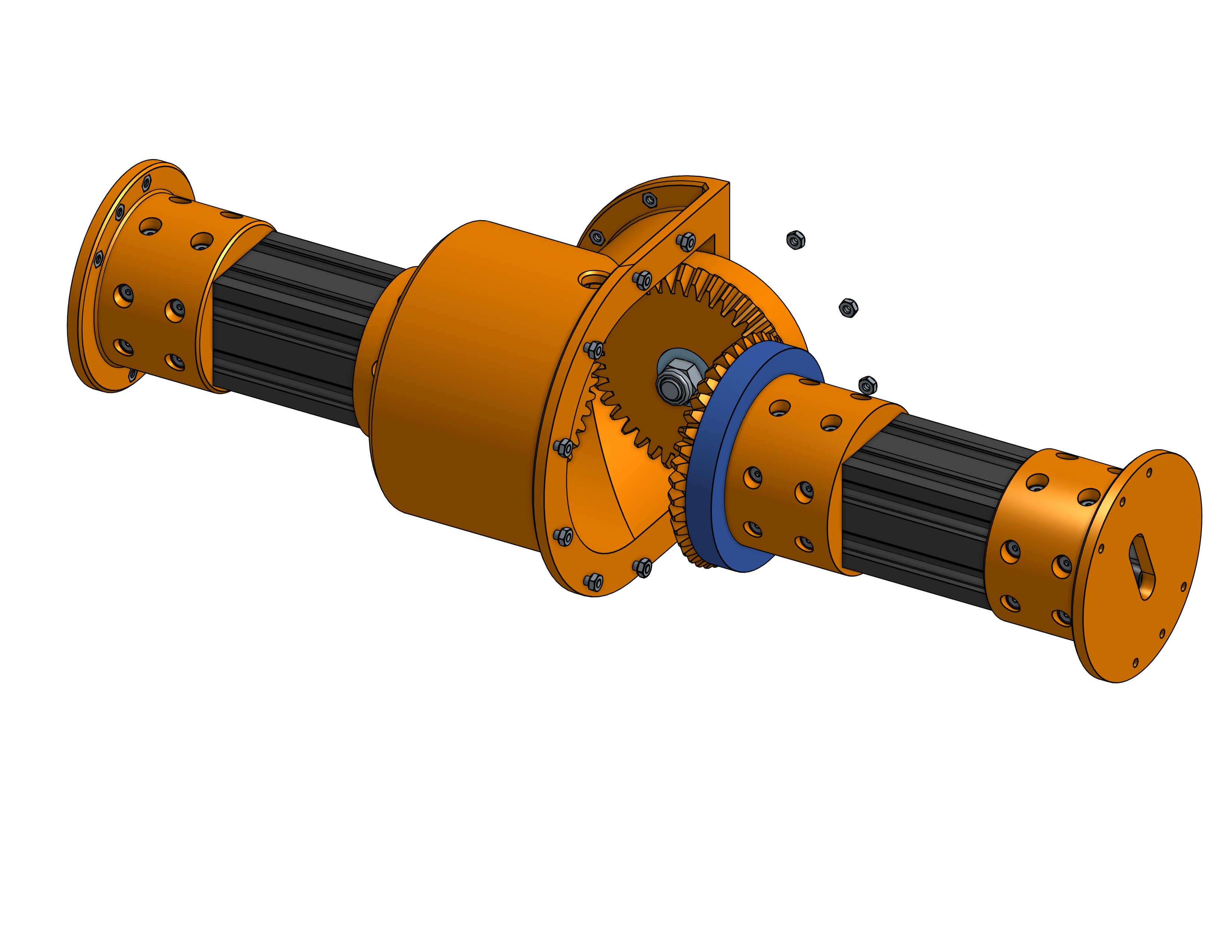
Extrusions, screws, and T-nuts
Both the rocker-bogie suspension and the body make heavy use of standard 2020, 2040, and 4040 aluminium extrusions. The printed parts connect everything together with an awful lot of M3 screws and T-nuts.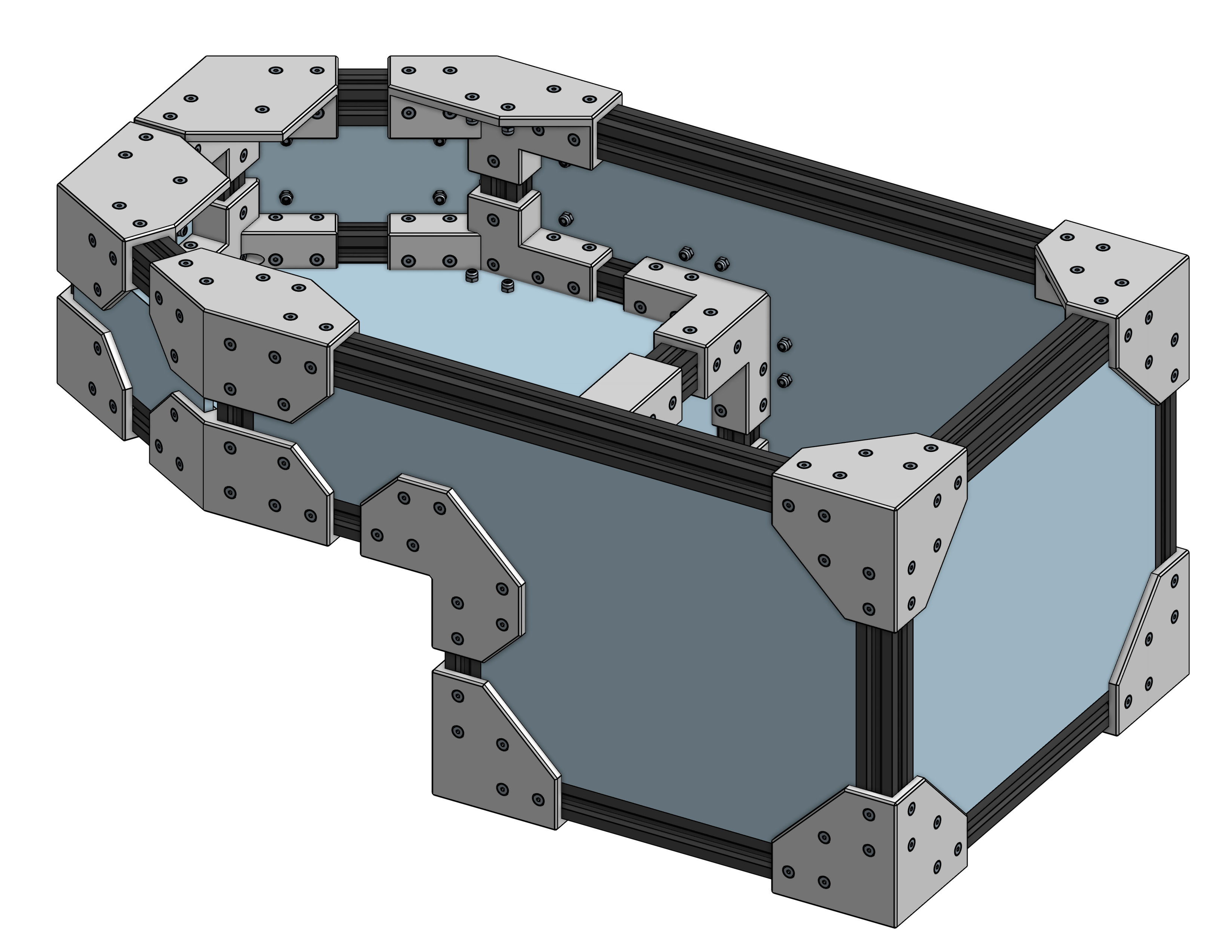
What’s next
I plan to redesign the differential’s centre gear and the bogie pivot to accommodate additional AS6500 position sensors. That will let us maintain an accurate picture of the suspension’s configuration as the rover moves across the terrain.
For now, the aim is to prove out the mechanical design with the parts we have. The paddock will no doubt have opinions about what needs to change.